
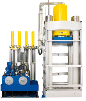
16MN laboratory press in column-type construction
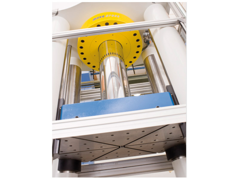
The 16MN laboratory press has been designed as a downstroke press (working cylinder bolted to the head plate, piston pointing downwards) with one cylinder and a working stroke of 1,000 mm. The maximum installation height between table and plunger is 2,200 mm.
The press is used, for example, for static compression, bending and tensile testing. The hydraulic and sealing system is not designed for dynamic tests. It is not allowed to carry out dynamic tests with this press. The press capacity must always act centrally onto the sample or tool. A backward movement of the working cylinder cannot be carried out in controlled operation.
The press is equipped with a simple, conventional hydraulic system to carry out high-speed movements in the low-pressure range for approaching the tool or for a quick opening of the press through touch buttons (manually) or through the control system (automati-cally). In automatic operation, these movements are monitored by displacement sensors as well as sensors at the final positions.
The pressure control in the high-pressure range is effected by four dynamically actuated servo gear-motors which act on the pressure transmitters through low-backlash spindle lifting elements and are operated alternately in pairs to maintain a continuous cylinder movement. Any effects on the outward movement speed of the working cylinder caused by varying pressures and oil volumes are largely compensated by the displacement measuring system and the control parameters.
A press capacity of 16MN is achieved at a maximum hydraulic pressure of 690 bar. The actual pressure values are monitored and transmitted to the control system by means of three digital high-precision pressure transducers in the pressure transmitters as well as in the working cylinder. The maximum control deviation is +/- 2 bar.
The setting values for force and displacement are transmitted by the PC software through an Ethernet interface to the press control system (Siemens S7). It is possible to transmit up to 20 segments, each consisting of one force or displacement value and one time value, to generate individual curves.
The press control system returns the actual values and status messages of the press to the PC. The actual pressure values are constantly monitored within the limits, which can be selected. This feature can be used, for example, to implement a tool breakage detection system.
Calculations of the pressure curves as well as the dynamic control of the servo motors and the comparison of set values and actual values are exclusively performed in the press control system.
The dynamic servo motor control system makes it possible to operate with very steep or very flat pressure curves without generating oscillations and the resulting pressure fluctuations in the hydraulic system. As only the servo motor is actuated for pressure generation in automatic operation the press has a very low noise level and is particularly suited for use in a laboratory.This type of control system has proven to be trouble-free and low-maintenance in long-term usage.
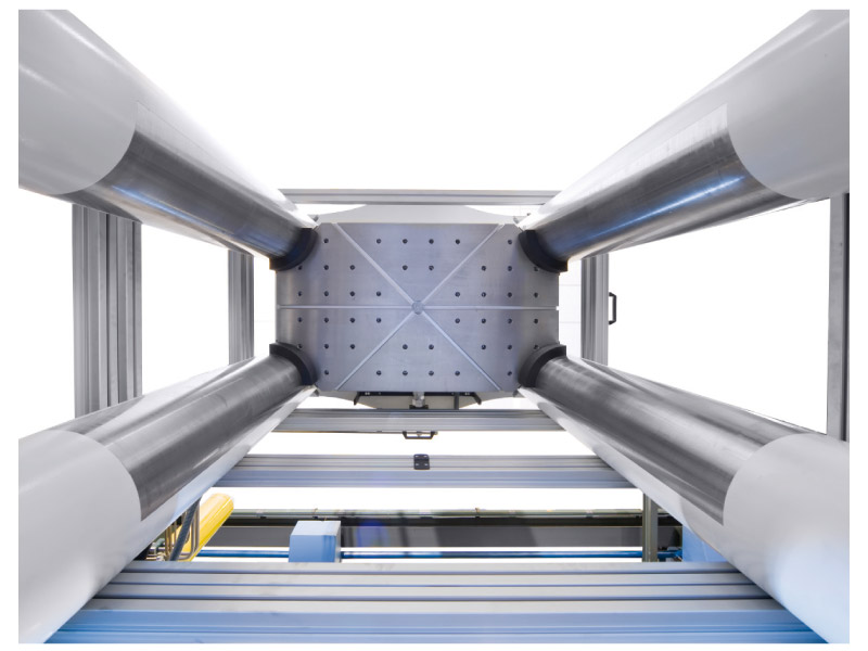
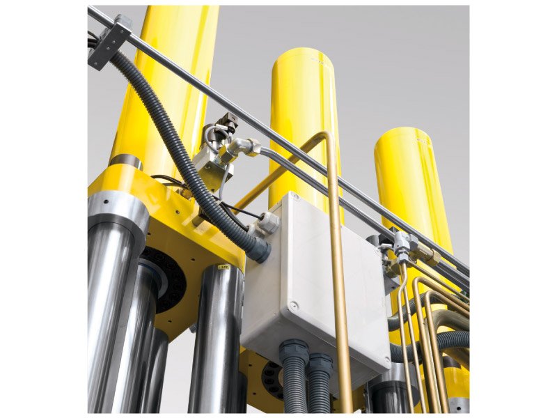
The frame of the press is formed by the head and tables plates in ground finish, which have been measured with static safety, and four round columns. The hydraulic system is located next to the press. The plunger of the press is guided over the round columns and secured against distortion. The press plunger or cross head cannot be adjusted to reduce the installa-tion height of 2,200 mm. The installation heights of the different tools are compensated for by spacer tables.
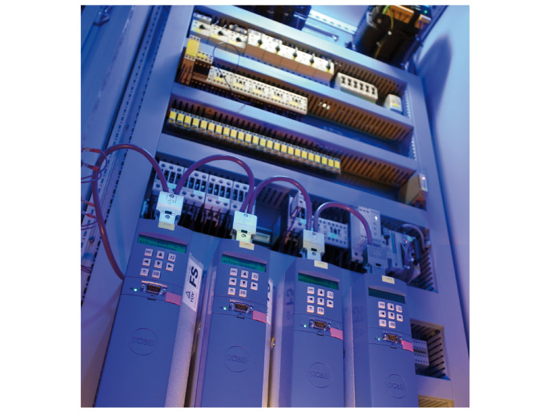
Programmable logic controller Simatic S7-300
One PLC (Simatic S7-300) controls the hydraulic aggregates, the valves and the servo drives. The pressures and the displacement of the main cylinder are read in digitally through Profibus-DP interfaces; during the replenishing procedure the pressure of the individual system is compared to the system pressure transducers.
The final spindle positions are transmitted to the servo controls via Profibus. The PLC transmits the status messages and fault messages as well as data to the process computer and transmits the force and displacement control settings from the process computer.
Emergency stop safety chain
If an emergency stop is actuated, all drives and valves are switched off in a safe position. The emergency stop chain must be reactivated after resetting of the switches by pushing the "control on" button.
Light curtain
Access to the press is monitored by a light curtain. As long as the press is open and the cylinder is secured with the clamp, it is possible to reach into the press area without any effect. Workpieces must only be exchanged when the machine is in this state, which is also displayed as "muting" at the operating panel on the control cabinet. Reaching through the light curtain during automatic operation will trigger an emergency stop and the process comes to a halt.
When the mains switch has been pushed, it is necessary to first acknowledge the light curtain and then to activate the emergency stop chain with the "control on" button.


Industriestraße 9-10
95336 Mainleus
Telefon +49 (0)92 29 / 306
Fax +49 (0)92 29 / 974163